


 ost pioneers in the field of magnetic resonance either built their machines themselves or modified existing equipment. In the 1950s, Erik Odeblad made his ground-breaking NMR measurements of tissues with a specially adapted spectrometer and in the 1970s Paul C. Lauterbur developed the idea of a whole-body imaging system with a design of his own (Figures 03-01 and 03-02).
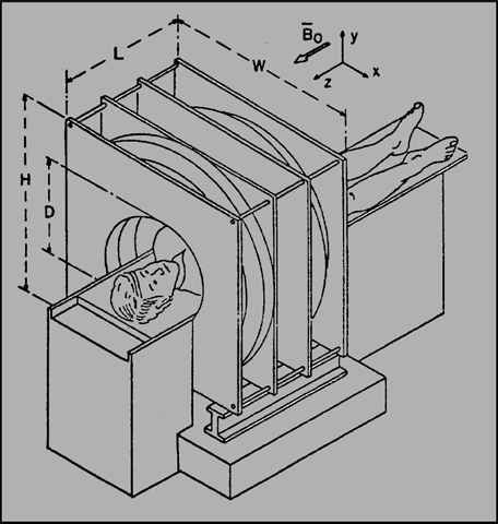
Figure 03-01:
A sketch of a possible magnet configuration for medical zeugmatography.
Graphic depiction from 1978 of what would become the first whole-body MR apparatus at Paul C. Lauterbur’s laboratory [⇒ Lai, House, Lauterbur]. The magnetic field was to be created by a resistive magnet system.
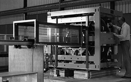
Figure 03-02:
One of the first commercial prototypes of an MR machine in 1984, based on a resistive magnet with a Faraday cage around the patient table. André Luiten, one of the early MR scientists at Philips, is standing next to it.
There is a wide variety of MR imaging systems and technologies. The extensive range of MR systems can be confusing for the potential buyer. Thus, they should identify their specific needs.
 The central part of the MR machine is the magnet. Its quality depends on three main criteria — it should create a static, stable, and homogeneous magnetic field. A static field does not vary over time. The earth's magnetic field is a static field, as is the field around a bar magnet. Both fields are also stable, which is a condition also required of a magnet used for MR imaging.The static magnetic field at one end of the sample to be studied must be exactly the same as at the other end: the field must be homogeneous.
Analytical NMR and MR imaging systems are very similar in their basic components. However, imaging machines additionally require gradient coils and Faraday shielding which protects the equipment against undesirable interference by radio waves from broadcasting stations transmitting on, or close to, the resonance frequency.
Any MR imaging equipment includes the following elements:
 a magnet large enough to house the sample to be examined (mouse or patient);
gradient coils and electronics;
RF-pulse transmitter and RF receiver;
power supplies and cooling systems;
a data acquisition and processing system, including a powerful computer;
operation and evaluation console(s).
A typical layout of an imaging system is depicted in Figures 03-03 and 03-04; in this case a mobile MR imaging unit is shown.
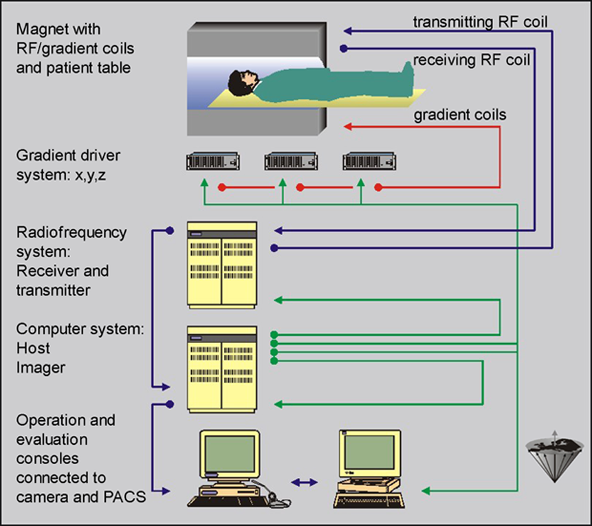
Figure 03-03:
The main components of an MR imaging system.
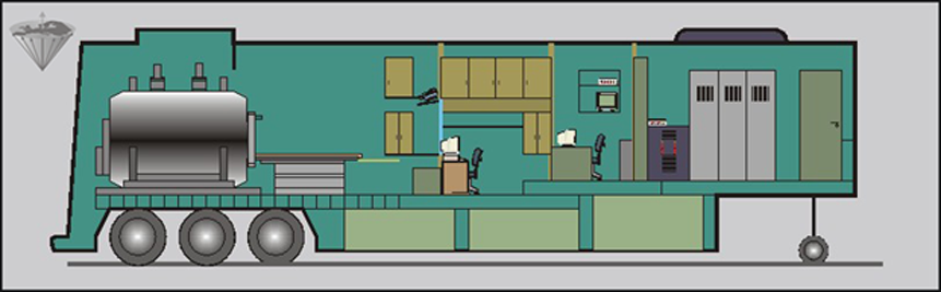
Figure 03-04:
Complete superconducting magnetic resonance imaging system (in a trailer). All necessary systems and subunits have been accommodated in limited space.
MR imaging systems are generally classified according to their magnetic field strength. The field strength can differ by several hundred percent according to the purpose of the equipment (Table 03-01).
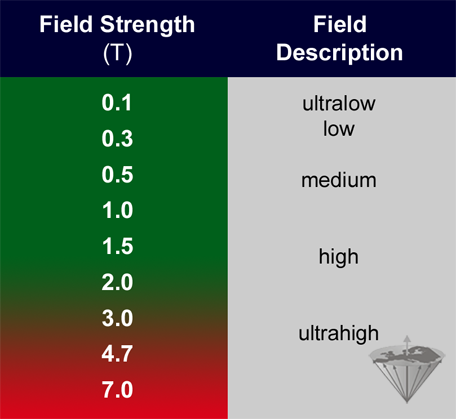
Table 03-01:
Definition of field strength, set by EMRF in 1989.
Up to 2 Tesla, there are only minor side effects of the magnetic field.
Paul C. Lauterbur's first whole body system operated at a field strength of 0.09 T. Such ultralow equipment (below 0.1 T) is hardly used any more. Most clinical machines operate at medium and high fields. For specialized applied research there is a trend towards ultrahigh field (UHF) whole-body machines, operating between 3 T and 14 T. Research machines with small bores for animal studies operate at even higher fields [⇒ Rinck 2021].
There is no optimum field strength for MR imaging for clinical diagnostics. The diverse nature of applications requires different systems operating at an appropriate field; a single perfect or ideal field strength for all clinical indications and/or research questions cannot be set.
Theoretically, one could perform MR studies at the earth's magnetic field — which has been proposed and done [⇒ Béné 1972]. Of course, the performance of equipment used at such low magnetic field is poor. More sophisticated approaches have been published by groups working at ultralow fields in the μT- and mT-range (ULF) [⇒ Inglis 2013, ⇒ Kraus 2014, ⇒ Sarracanie 2015].
ULF MRI has a very limited spatial and temporal resolution. These systems are not really comparable to or even competitive with current clinical MRI systems, their developers are primarily envisioning deployment in remote areas or low-income countries — they are intended for diagnostic questions not answerable with existing imaging techniques in these countries. In terms of clinical usability and pricing they compete with ultrasound, a much more versatile imaging technology at a similar price, or simple CT scanners [⇒ Hennig 2023].
There is an increased incidence of physiological hazards in the red area of Table 03-01. For further details on possible hazards and side effects of magnetic fields, especially at field strengths beyond 2 T, refer to Chapter 18.
An old topic in MR imaging, yet always fashionable:


|
Chapter 3 — Page 1 |

|
|---|
