


 hortly after the introduction of MR as a new imaging modality, it was hailed as a technique which did not suffer from the common beam hardening artifacts which can destroy images in x-ray computed tomography.
However, it was soon realized that an unfortunate side effect of the complex nature of MR imaging was a whole new set of artifacts. Artifacts (sometimes also called artefacts in British English) in MR images can take the form of variations in signal intensities or mispositioning of signals (Figure 17-01).
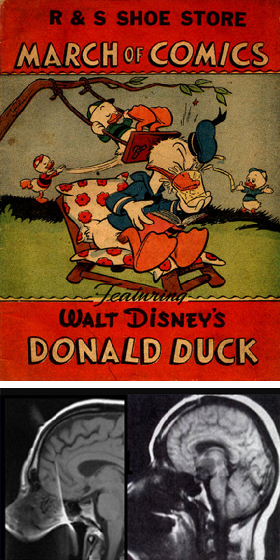
Figure 17-01:
If the sagittal MR image of a head that you get on your screen reminds you of Donald Duck and his nephews, there is something wrong — either with your patient or with your MR equipment.
It might be Donald Duck artifacts caused by dentures.
Artifacts can be categorized into four main groups which we will discuss in this chapter:
 magnetic field perturbations;
RF and gradient related artifacts;
motion and flow artifacts;
signal processing and mapping artifacts.
magnetic field perturbations;
RF and gradient related artifacts;
motion and flow artifacts;
signal processing and mapping artifacts.
Usually artifacts are easily recognized when their causes are known. They can spoil images and make them useless for diagnostic purposes, but they also can mimic pathology to such an extent that examinations have to be redone, other diagnostic modalities have to be used to exclude pathology (Figures 17-02 and 17-03), or they can even lead to surgical intervention because pathology was falsely described.
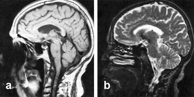
Figure 17-02:
Sagittal midline images through a head.
(a) Intermediately weighted image, and (b) T2-weighted image. On the left image, a low signal intensity area is seen in the pons, suggesting a lesion. This lesion is not visible on the T2-weighted image. It is caused by image distortion created by ferromagnetic implants.
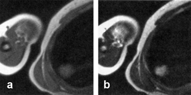
Figure 17-03:
(a) Transverse intermediately, and (b) T2-weighted images depict an ill-defined high signal intensity lesion in the right lung. Follow-up studies on another day and the use of CT did not show such a lesion. The cause of the artifact remained unclear.
 Table 17-01 summarizes some of the most common artifacts and their remedies. Most of them are covered on the following pages.
However, artifacts caused by defective components, malfunctions of the equipment, or artifacts connected to the equipment of specific manufacturers — in particular those created by 'black box' software — might be different from the common artifacts covered in this chapter.
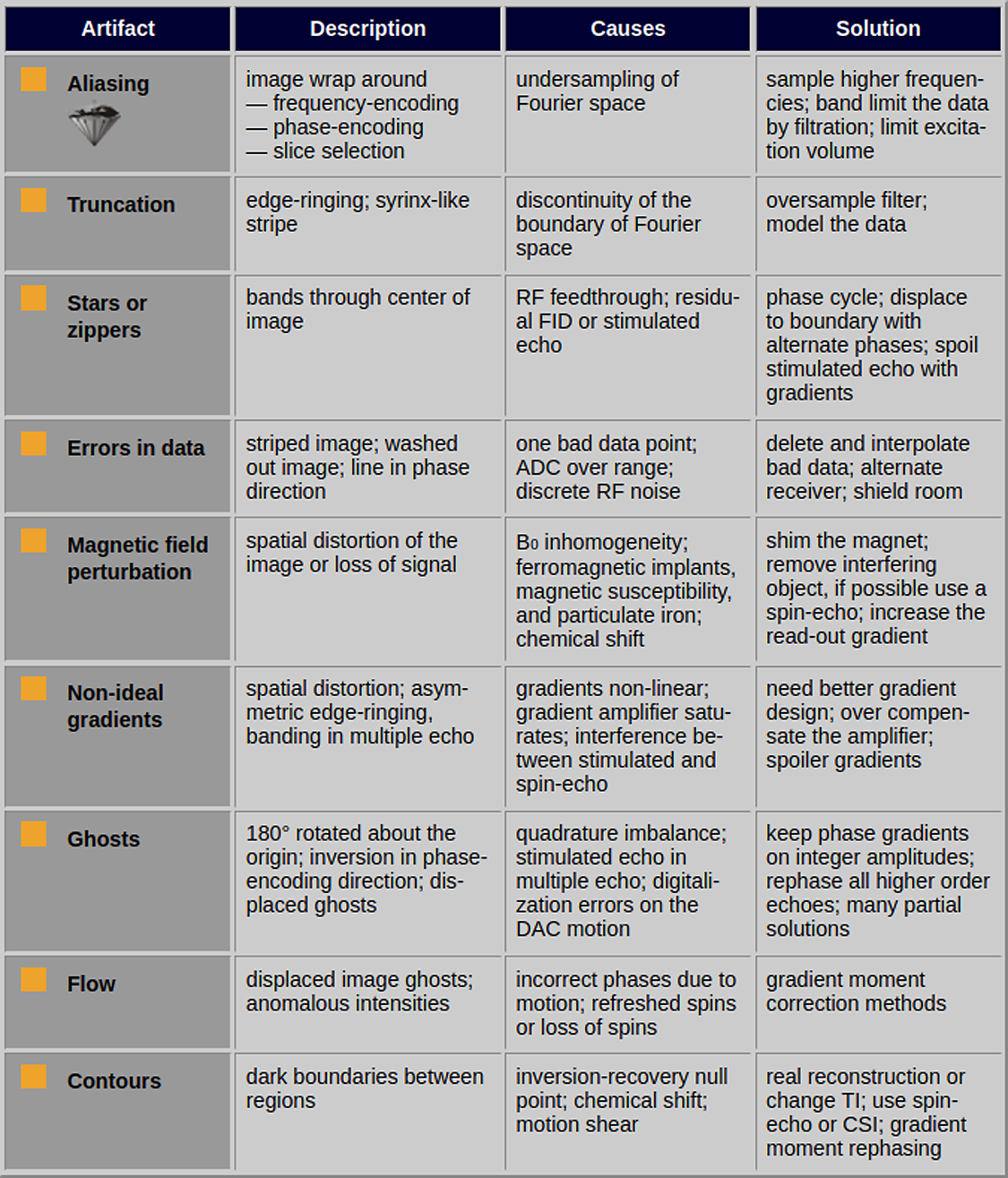
Table 17-01:
Image artifacts and remedies. Modified from papers by ⇒ Henkelman 1987 and ⇒ Johnson 1989.


|

|
|---|