


 adiofrequency directed at one slice might interfere with the excitation of a neighboring slice. This undesired excitation is also known as cross excitation or crosstalk (Figure 17-06).
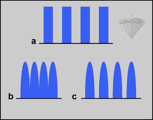
Figure 17-06:
(a) The ideal pulse shape is the square pulse which precisely defines the slice and homogeneously excites all spins within this slice.
(b) However, the actual pulse profile tends to be Gaussian. These pulses can overlap and deliver RF energy to neighboring slices.
(c) Increasing the interslice gap decreases the energy delivered to neighboring slices.
The effects of cross excitation are changes in image contrast (cf. Chapter 6). Countermeasures include an increase of interslice gaps or non-sequential excitation of anatomical slices.
The slice profile of an RF pulse can be distorted when repetition times not allowing full recovery of the signal are used [⇒ Young 1987]. For any given profile, there is always a transition zone where the value of the flip angle goes from zero up to the desired value. In the case of incomplete recovery of the magnetization, the strongest signal is produced at a flip angle which is less than 90°. The slice profile will therefore show maximum peaks on either side of a central dip.
This becomes particularly acute when very short TR values are used in conjunction with a large flip angle (e.g., spoiled FLASH sequence with good T1 contrast).
In such cases the desired contrast is not obtained since we will have a mixture of contrasts due to the variation in the flip angle across the slice. This can be overcome by using RF pulses which give very sharp transition zones or by using a 3D sequence.
Multiple spin-echo (MSE) or SE-based sequences are widely used in MR imaging. Problems can arise with such sequences due to the fact that the refocusing pulses will not be perfect 180° pulses across the whole slice, and in the transition zone (from 0° to 180°) at the edge of the slice, a whole range of flip angles will be present.
This means that the refocusing pulses will not only form the desired spin echoes, but also will generate other signals which, if not suppressed, can degrade the images obtained from the second echo onwards [⇒ Graumann 1986].
There are a number of solutions to this problem including the addition of spoiler gradients to the sequence (which increases the minimum echo times) or the use of phase-cycling to cancel out the unwanted components (which increases the overall scan time).
It is also possible to move the artifacts to the edge of the image by using suitable phase schemes for the RF pulses. This generally reduces their effect on the region of interest.
A relatively common artifact is the presence of a high intensity line (sometimes looking like a zipper) at the center of the image, orientated in the phase encoding direction. This is usually caused by RF leaking from the transmitter to the receiver. Since the leakage is at the resonance frequency, it will appear at the center of each projection.
Slight variations in the amount of leakage in each projection cause the artifact to be smeared out across the field-of-view in the phase-encoding direction. This problem can be difficult to track down and eliminate completely, but can be removed by collecting two averages in conjunction with phase alternation of the excitation pulses.
Line artifacts in the phase-encoding direction away from the center of the image usually result from RF interference at a well-defined frequency. For the most part they are caused by polluting RF, e.g., commercial radio or television stations. Commonly, the RF shielding supplied with commercial systems is adequate, but the door seals should be checked and cleaned periodically.
 Central point artifacts are white or black dots in the center of the MR image. They are only seen on older MR equipment.
A line artifact as a k-space artifact is shown in [Figure 17-18].


|

|
|---|